

75PS power supplies
 |
|
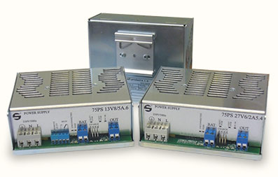
These power supplies are intended for general use to feed electric and electronic devices with direct voltage in covered rooms, in environments without risk of explosion. Output voltage can be in range from 4,2 V to 55,2 V. The power supply is designed to be mounted on a DIN rail, however it is possible to mount it with screws with a piece of DIN rail that is now a standard equipment of every 75PS power supply.
Nominal output voltages and corresponding max. output currents are listed in table below. The power supply is protected against short-circuit on the output. The connection of input and output wires is realized through screw clamps. Input and output clamps are not protected against touch to dangerous voltage. This protection must be provided by the customer.
|
|
|
Table 2: Models of 75PS power supply
|
Output voltage |
Output current min. |
Stability |
Ripple 100 Hz |
Noise | |
|---|---|---|---|---|---|
| 75PS04V2/7A.x | 4,2 V | 7 A | <2 % | <20 mV | <50 mV šš |
| 75PS05V/7A.x | 5 V | 7 A | <2 % | <20 mV | <50 mV šš |
| 75PS06V/7A.x | 6 V | 7 A | <2 % | <20 mV | <50 mV šš |
| 75PS06V9/7A.x | 6,9 V | 7 A | <2 % | <20 mV | <50 mV šš |
| 75PS09V/7A.x | 9 V | 7 A | <2 % | <20 mV | <50 mV šš |
| 75PS10V/7A.x | 10 V | 7 A | <2 % | <20 mV | <50 mV šš |
| 75PS12V/6A.x | 12 V | 6 A | <2 % | <20 mV | <50 mV šš |
| 75PS13V8/5A.x | 13,8 V | 5 A | <2 % | <20 mV | <50 mV šš |
| 75PS15V/5A.x | 15 V | 5 A | <2 % | <20 mV | <50 mV šš |
| 75PS16V/4A5.x | 16 V | 4,5 A | <2 % | <20 mV | <50 mV šš |
| 75PS17V/4A.x | 17 V | 4 A | <2 % | <20 mV | <50 mV šš |
| 75PS18V/4A.x | 18 V | 4 A | <2 % | <20 mV | <50 mV šš |
| 75PS20V7/3A5.x | 20,7 V | 3,5 A | <2 % | <20 mV | <50 mV šš |
| 75PS24V/3A.x | 24 V | 3 A | <2 % | <20 mV | <50 mV šš |
| 75PS27V6/2A5.x | 27,6 V | 2,5 A | <2 % | <20 mV | <50 mV šš |
| 75PS48V/1A5.x | 48 V | 1,5 A | <2 % | <20 mV | <50 mV šš |
| 75PS55V2/1A3.x | 55,2 V | 1,3 A | <2 % | <20 mV | <50 mV šš |
| .x – this number specifies the sort of additional functions (see below) | |||||
Additional functions on power supply (marked with .x):
| .1 | .2 | .3 | .4 | .5 | .6 | |
|---|---|---|---|---|---|---|
| Output voltage clamps |
 |
|
|
|
|
|
| Operation signalization with green LED |
|
|
|
|
|
|
| Twin output clamps |
|
|
|
|
|
|
| Operation signalization with 10 V voltage on external clamps |
|
– | – | – |
|
– |
| Operation signalization with switching relay contact – galvanically separated | – | – |
|
– | – |
|
| Possibility to disconnect the power supply with external voltage 10–15 V |
|
– |
|
– |
|
|
| Signalization of current flow overload from the power supply – orange LED |
|
|
|
|
|
|
| Functions available only for accumulator versions, ie. 13V8 and 27V6 | ||||||
| Accumulator clamps – replace second output clamps |
|
|
|
|
|
|
| Circuit with accumulator protected with car fuse |
|
|
|
|
|
|
| Signalization of broken car fuse with red LED |
|
|
|
|
|
|
| Signalization of disconnected or opposite connected accumulator with red LED | – | – | – |
|
|
|
| Setting of charging current to accumulator in four steps | – | – | – |
|
|
|
| Accumulator disconnector – disconnects positive pole to prevent deep discharge | – | – | – |
|
|
|
| Signalization of current flow overload in accumulator circuit – orange LED | – | – | – |
|
|
|
Description of additional functions:
| Accumulator disconnector |
— Disconnector serves as a protection to prevent a deep discharge of the accumulator. That means when the voltage on output clamps drops below 10,5 V (21 V) the disconnector galvanically disconnects positive pole from the circuit. The accumulator now stores only small fraction of energy and the voltage it is supplying drops fast. During further voltage drop the accumulator would be irreversibly damaged. — Disconnector connects the voltage back to accumulator clamps only in case that there is a battery connected with correct polarity and with voltage of at least 30 % of the nominal value. — After disconnecting the accumulator during operation, circuit between output clamps and AKU clamps will not be interrupted. — Disconnector connects AKU clamps with output clamps only after the power supply is turned on. — When the power supply is turned off and accumulator is connected, power supply’s consumption is approximately 10 μA. — During power network outage the disconnector keeps AKU clamps connected with output clamps until the voltage drops below 10,5 V (on a 13V8 power supply) or 21 V (on a 27V6 power supply) – after that it will disconnect the circuit. — To switch back to on-state, first the power supply must start. — When exceeding total current consumption, ie. current drawn from output plus current needed for charging of accumulator, it leads to limitation – output voltage gradually drops. Accumulator then starts to act as a source of current and total current consumption is given by the sum of max. output current of the power supply plus current from the accumulator, which is limited only by the fuse. If the fuse will not blow due to enormous overloading, this situation is time-limited only by accumulator’s capacity. While discharging, the accumulator’s output voltage drops and when it drops below values as specified before, the disconnector will disconnect it from the circuit. The accumulator will be connected back to the circuit only when the load drops to a such level that will allow the output voltage to rise at min. 12 V on a 13,8 V power supply and 24 V on a 27,6 V power supply. — In case that the power supply is an accumulator version and the accumulator is disconnected or connected with reverse polarity, a red LED will light up when the power supply is switched on. The accumulator can be connected also while the power supply is in operation, but it is risky because when the accumulator is disconnected the AKU clamps will not be disconnected from the output clamps and connecting an accumulator with reverse polarity will lead to short-time high value currents leading to the damage of power supply, or eventually to the damage of feeded device. |
| Current setting to AKU | — This function allows to set the maximum current to charge an accumulator (but does not limit the current that the accumulator can supply) in five values by using a jumper, ie. for 13V8 – 1A, 2A, 3A, 4A and 4,5A or for 27V6 – 0,5A, 1A, 1,5A, 2A and 2,25A. Last value indicates max. current when the jumper is not used or is defective. When setting the value of max. charging current to the accumulator, it is desirable to take into consideration manufacturer’s data regarding max. charging current and also dimensioning of currents in circuit. |
| Operation signalization |
— Galvanically connected – on external clamps there is approximately 10 V voltage during operation. Negative pole is connected with negative pole of output voltage. — Galvanically separated – switching relay contact with max. load of 1A/125VAC or 1A/24VDC. |
| External switch off |
— By connecting a voltage of 10–15 V on clamps the power supply will switch off without the need to disconnect AC input. The input is galvanically separated with optocoupler with breakdown strength of 5 kV. — With this function it is possible to simulate a power grid failure and check the operation of the whole set in this mode, including for example measuring the voltage of accumulator. If the controller unit allows such feature, these measurements can be done remotely and in specified intervals. |
|
Signalization of broken car fuse |
— In case of broken fuse and switched on power supply a red LED will light up. |